

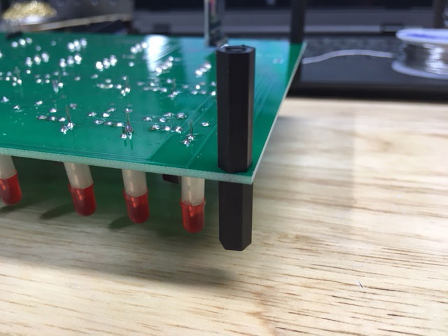
- When you add the rear panel, the mounting of the PC board is slightly different. First, add the 14mm male/female standoffs on the top, and two 20mm male/female standoffs on the side with the Arduino.
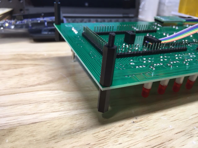
- On the other side add the 14mm male/female standoffs on the top, and two 20mm female/female standoffs on the bottom.
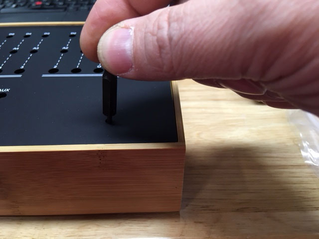
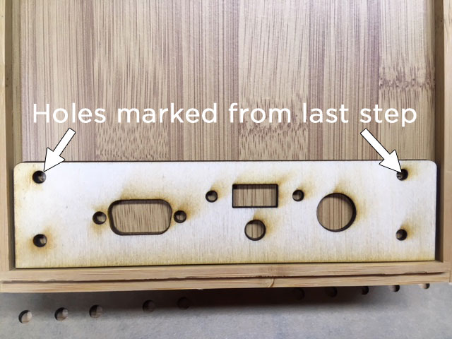
- Mark the location of the mounting holes for the PC board and front panel. You can do this by putting the front panel in place and using a 1/8" (or 3mm) drill bit to mark the holes in the bottom of the bamboo case.
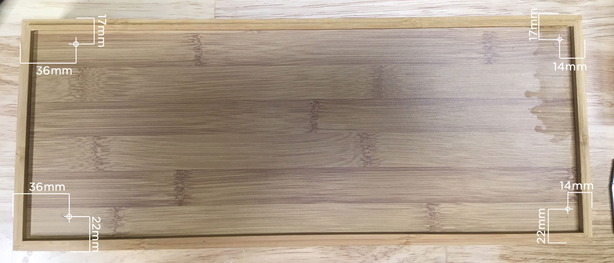
- If you prefer not to "eyeball" the location of the mounting holes, you can place them using these measurements (from the edge of the box to the center of the hole): 17mm x 36mm 22mm x 36mm 17mm x 14mm 22mm x 14mm Click image for a larger view.
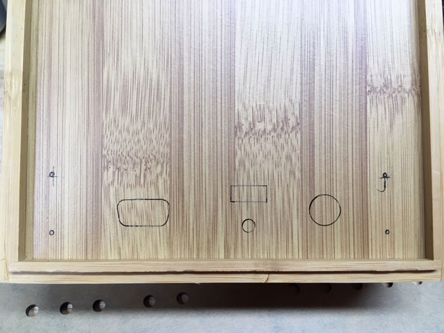
- Place the rear panel with the top two hole cutouts over the holes you just marked (the two holes 36mm from the edge of the box.)
- Draw marks inside the rear panel cutouts. These will serve as a guide to drill the holes and cut access for the panel.
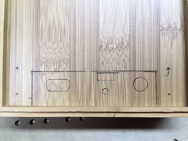
- Draw a box around the components large enough to fit everything.
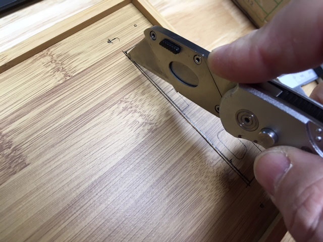
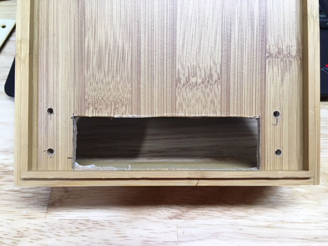
- Cut the area you just marked with an X-acto knife or utility knife. Don't worry if it's not square or perfect, just make sure it will be covered completely by the rear panel.
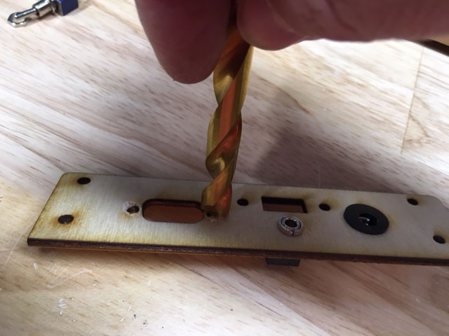
- Your cutout should look like this. Drill the locations you marked for the holes with a 3mm or 1/8" drill bit.
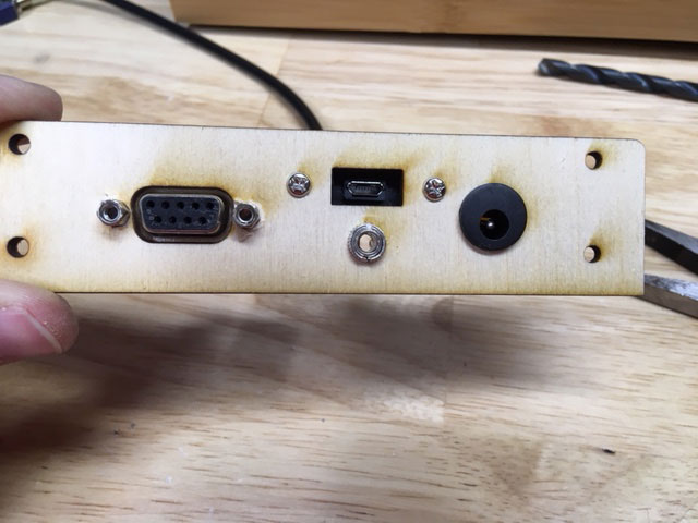
- Now you will mount the components in the rear panel. Start by placing the DC power jack and tighten the nut.
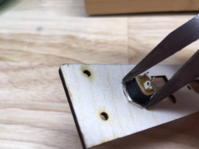
- Before mounting the audio jack, use a larger drill bit to shave some away from the back of the panel (by hand, not with a power drill) so the jack will be inset into the rear panel. This will allow the nut to better grip the jack.
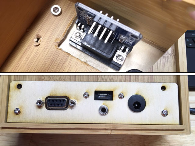
- Remove the standoff hex nuts from the MAX3232 serial module.
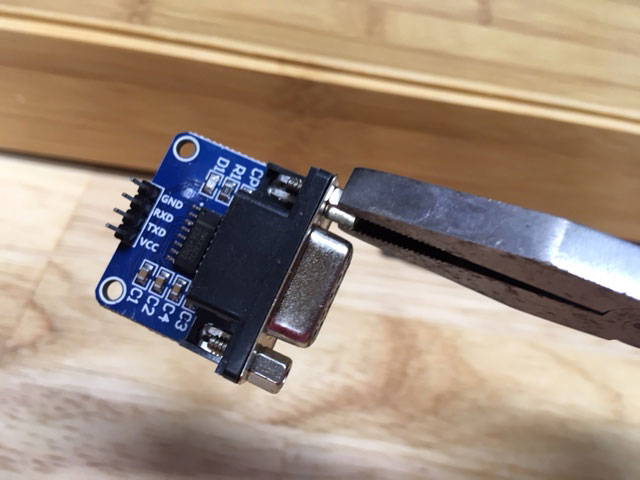
- The standoff hex nuts will probably be too short to secure the serial module to the rear panel. One thing you can do is to remove the metal shroud from the serial module. It will still work with no issues.
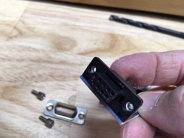
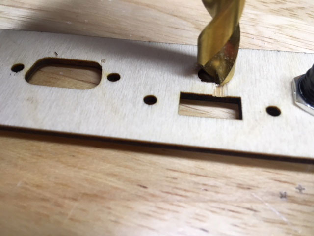
- Personally, I like the look of the metal shroud and prefer to leave it in place. Instead, you can use a larger drill bit and use it to shave a bit off from the front of the rear panel as shown (again, by hand not with a power drill.)
- The standoff hex nuts will secure the module and will be inset into the rear panel.
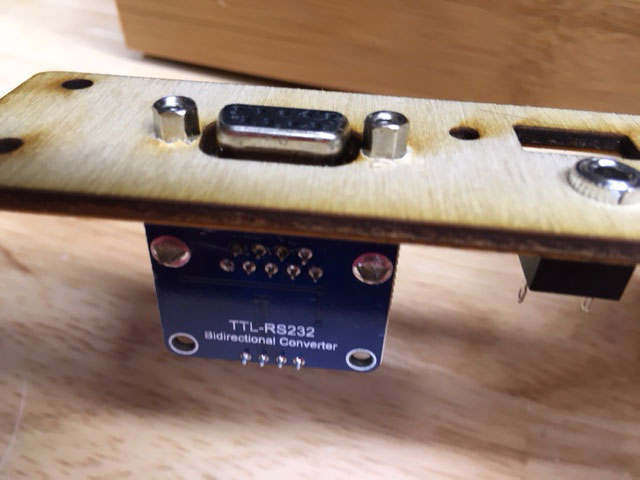
- Next you will mount the USB panel extension. The extention mounts to the rear panel with two 8mm steel screws.
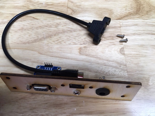
- Here is the finished rear panel.
- Attach it in place to the bamboo case with the bottom two screws only (with washers and nuts).
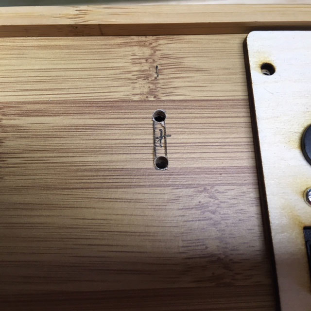
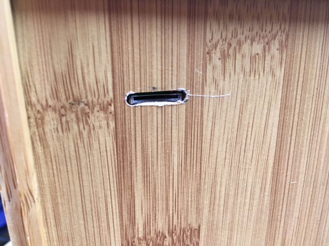
- If you want access to the micro SD card from the outside of the case, you will need to cut a slot for it. Mark a point that is 65mm x 37mm (see photos.)
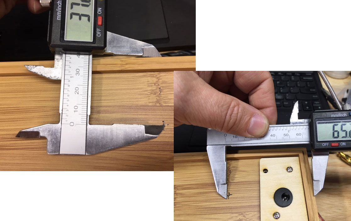
- That is the center point of the slot. Draw a 16mm x 3mm rectangle around that point.
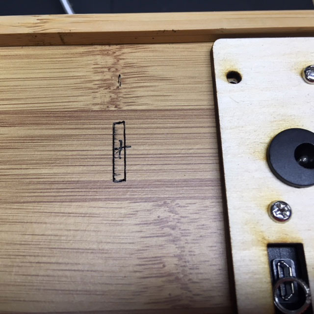
- Drill a 3mm or 1/8" hole in the top and bottom of the slot, then cut between them with a X-acto or utility knife.
- Solder a pair of wires at least 35cm long to the power jack. Note the polarity in the photo.
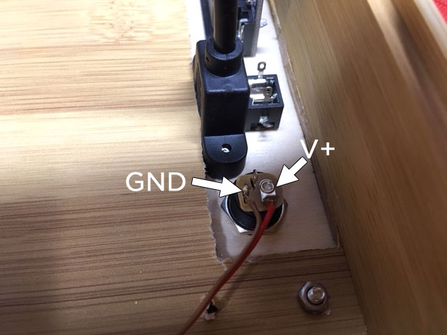
- Solder the other ends to the power input on the opposite side of the PC board. Make sure there are no shorts, and that you don't reverse the polarity.
- Here are the connections for the audio jack.
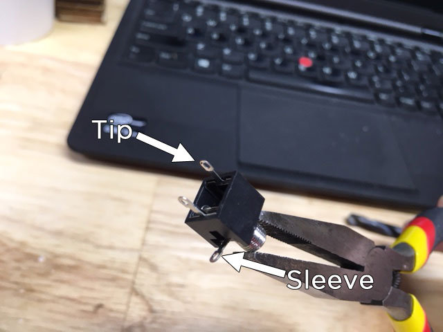
- Audio jack connects to the opposite side of the PC board as the power connections.
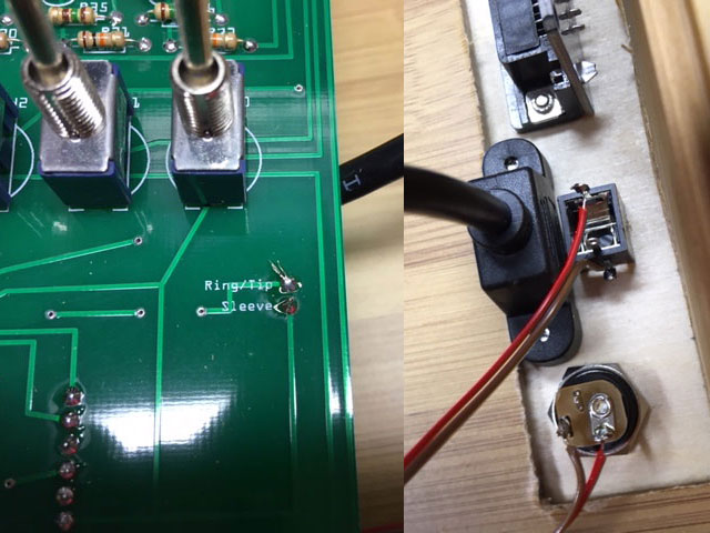
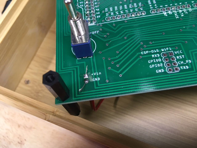
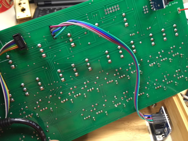
- Connect the serial port module to the PC board. You should have a four-pin part of the Arduino header left over, solder this to the underside of the PC board – this is where the serial cable will plug in. The pins are labeled on the top of the PC board and on the serial module. Please note: this is not a “straight through” connection. Make sure the matching labels are connected properly.
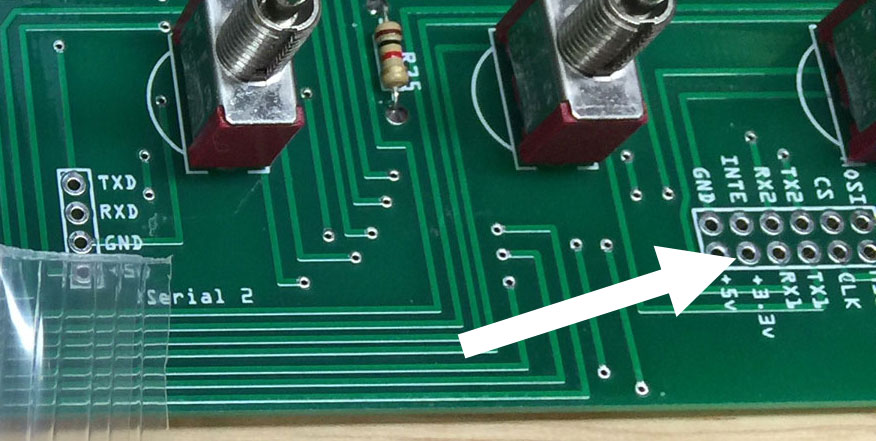
A few guys over on our user forum have pointed out that the serial port module should be powered with 3.3v instead of 5v to prevent damage to the input pins on the Arduino Due.
I have not had an issue with damage to the Arduino, but just to be safe you can connect the Voltage-In pin on the module to the 3.3v connector just a few centimeters to the right (you still should have an extra header pin for that!)
- Connect the USB extension to the programming port on the Arduino.

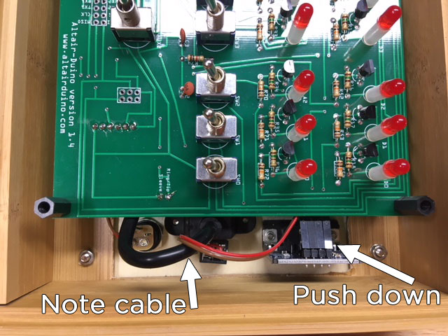
- It's time to put the completed circuit board into the case. You will have to gently push down the connector for the serial module to slightly bend down the pins. Also note the orientation of the USB extension cable, this will keep it out of the way of the PC board.
- If you put the SD card in before you do the final assembly, it will help you guide the SD module into place in the slot you cut in the case.
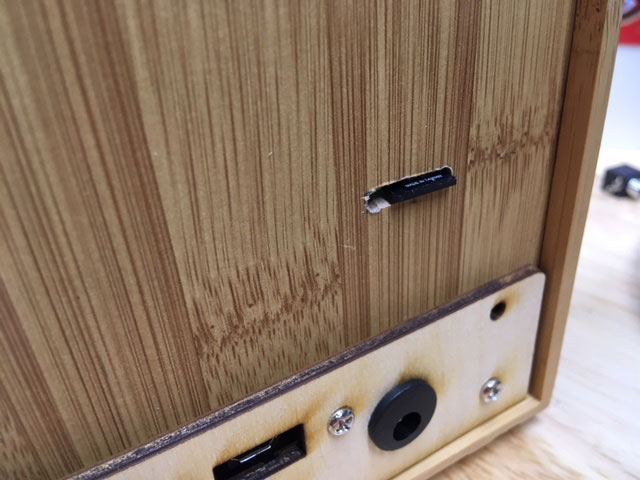
- This is how the SD card module will look when properly seated in a 3mm x 16mm slot.
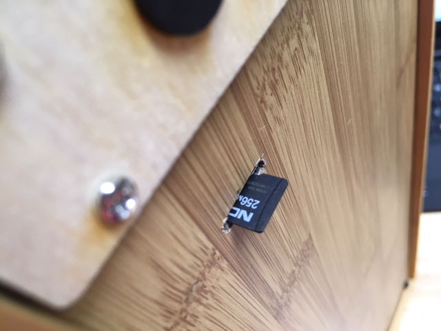
- When installed, the micro SD card will stick out about 1/4 inch (6mm).
HINT: If you have loaded the disk images on the card and see nothing but a non-stop sequence of “c” when you access the card, you need to completely reformat the card (FAT or FAT32, be sure to select FULL format, not a quick format.)
Better yet, I strongly suggest downloading the SD card formatter from the SD Association.
I have have built dozens of Altair-Duinos and every time the SD card functions correctly, but I have run into a couple circumstances where the micro SD card I was trying to use *absolutely* would not work. I don’t know why, but apparently it can happen. Then your only choice is to try a different card. A few guys have reported that reloading the Arduino software has helped them.
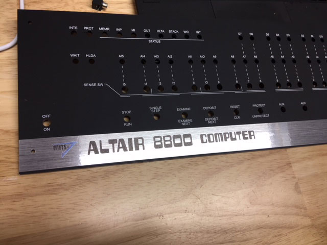
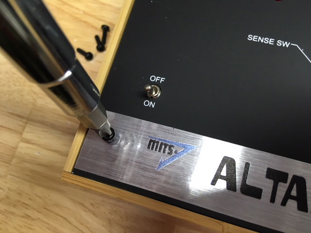
- Apply the Altair 8800 sticker to the front panel. The adhesive is forgiving, so if you place it wrong, you can pull it up and put it in place again. Use a small Phillips screwdriver or awl to poke holes where the bolts will go.
- Put the front panel in place, push down around the LEDs and switches to set it properly, and add the 10mm nylon bolts.
If your case seems a little tight (it’s wood so it tends to expand/contract with temperature and humidity) you can easily trim it a bit with an X-Acto knife.