
Parts List
- 1 x PC Board
- 36 x 5mm Red LED
- 36 x 12mm LED Standoff
- 36 x NPN Transistor
- 36 x 150Ω Resistor
- 36 x 10kΩ Resistor
- 17 x Mini Toggle on-off
- 8 x Mini Toggle (on)-off-(on)
- 1 x 470Ω Resistor
- 1 x 47µF Capacitor
- 1 x Arduino Due
- 1 x Front Panel
- 1 x “Altair 8800” Metallic Sticker
- 1 x Project box (optional)
- 1 x Micro SD Module
- 1 x HC-05 Bluetooth Module OR 1 x MAX3232 DB9 Serial Port
- 1 x DC-022 Power jack
- 1 x 12v Power Supply
- 2 x 8 Pin Cable
- 1 x 6 Pin Cable
- 4 x 14mm Standoff
- 4 x 20mm Standoff
- 4 x 3mm Screws
- 4 x 3mm Nuts
- 1 x Dual Pin Header
- 2 x Single Pin Header
- 1 x USB Cable
Other Parts You May Need
- Soldering Iron with a nice fine tip
- Good Solder (I recommend Alpha Fry Rosin Core 0.032” Solder)
- De-soldering Iron or Pump (optional)
- Flat Screwdriver
- Needle-nose Pliers
- Side Cutters (Nippers)
- Drill with 3mm or 1/8″ and 12mm or 1/2″ bits
- Micro SD Card (1GB is sufficient)
- Computer
You do not have to follow the exact order of assembly I have laid out below. One of the very excellent suggestions I have received is to put the switches in the pc board (without soldering) then use the front panel to hold them in the correct position while soldering. Then, remove the front panel and add the LEDs/spacers (again without soldering) and use the front panel to hold them in place while soldering. I’ve tried this method a couple times and it works very well.
If you didn’t choose to receive a pre-programmed Arduino, you will have to upload the software at some point. You can do that by following the instructions on this page.
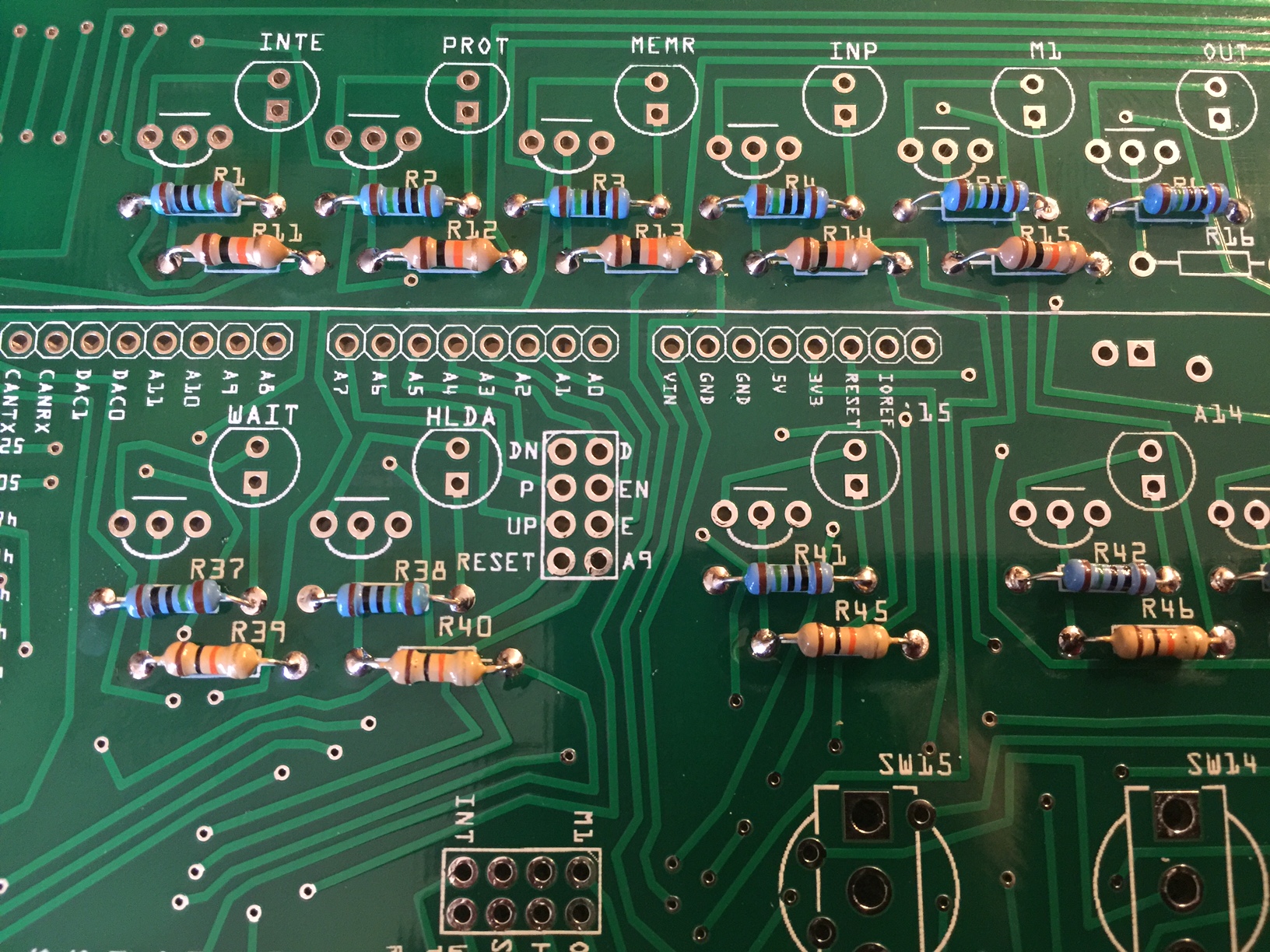
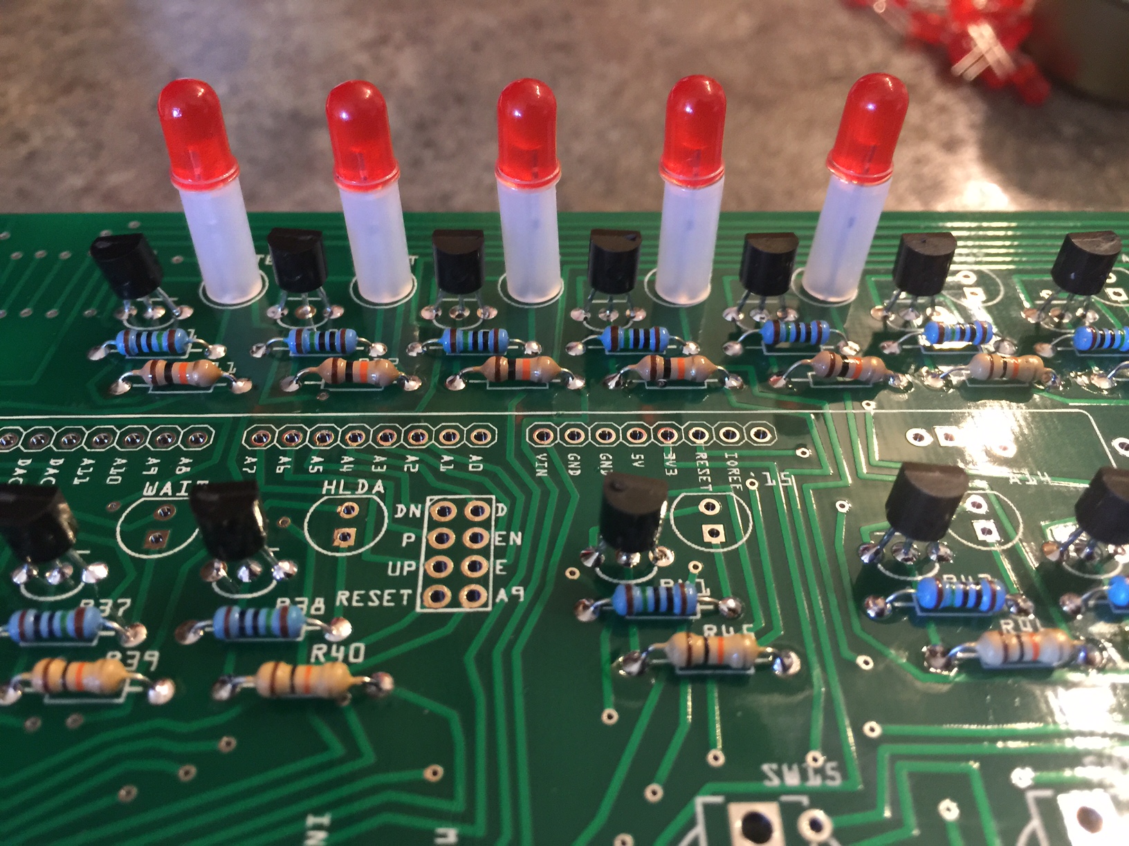
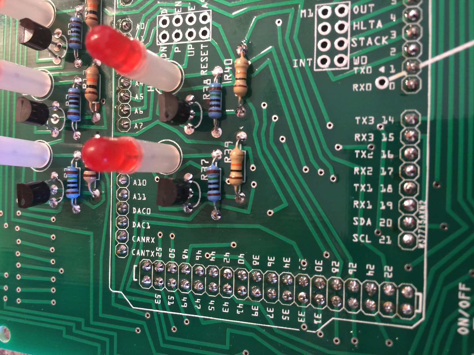
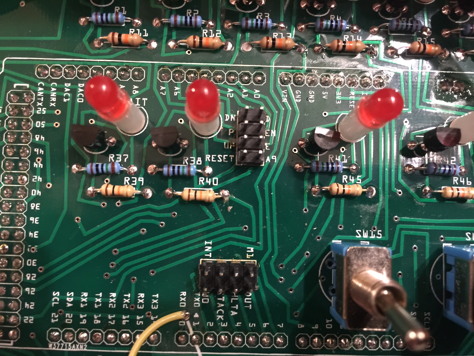
- Start by adding 36 150Ω resistors to the top rows under the LED/Transistor pairs in locations R1-R10, R21-R28, R37, R38, R41-R44, R49-R51, R55-R57, R61-R63, R67-R69 (in retrospect, I should have numbered these consecutively!) Resistors are non-polarized, meaning they can go in either direction, you do not need to worry about orientation.
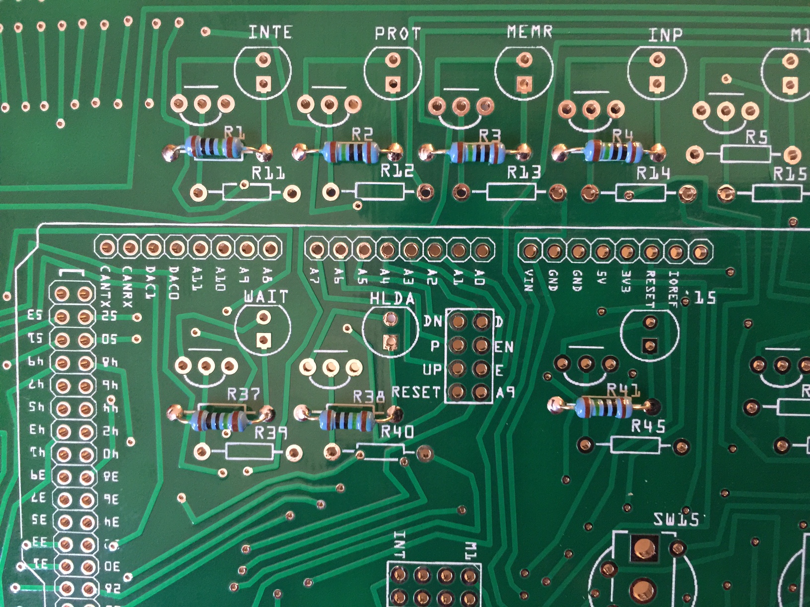
- Next, add 36 10kΩ resistors to the second row in locations R11-R20, R29-R36, R39, R40, R45-R48, R52-R54, R58-R60, R64-R66, R70-R72.
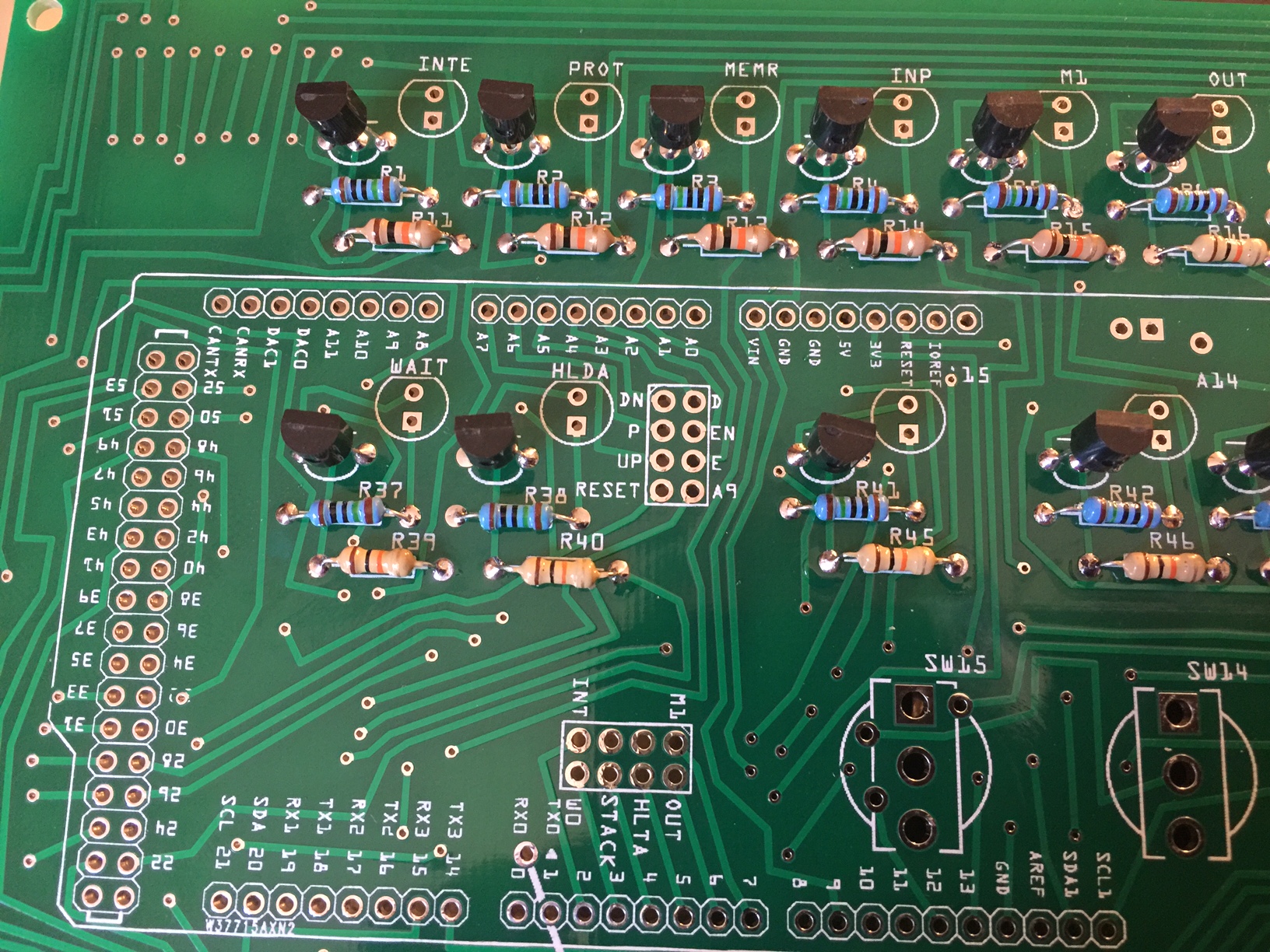
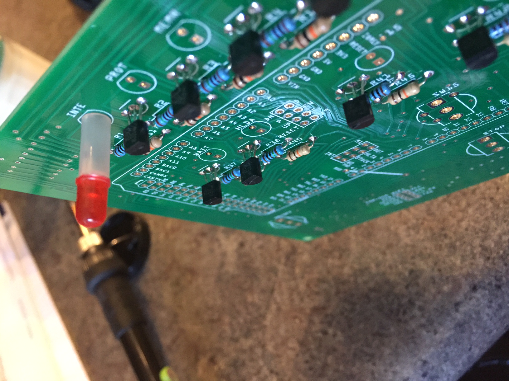
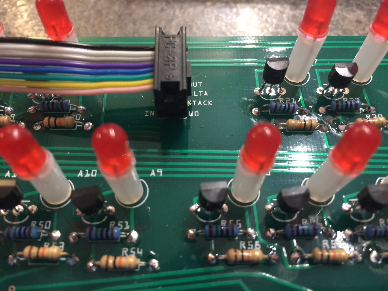
- The 36 transistors are added next. The orientation of the transistor is crucial, but relatively simple. Just make sure the flat end of the resistor is facing up, just like the image printed on the circuit board.
- (After assembling this kit a few more times, I would definitely suggest waiting to solder the LEDs until after all other components, using the front panel to hold them securely while you solder them.)
36 LEDs and spacers are next. Insert each LED in the spacer (with the dual holes facing up) and be sure to solder in with the correct polarity. The long lead of the LED should be toward the bottom of the circuit board, with the flat end of the LED toward the top (or, if you notice, the long lead of the LED goes in the square hole.)
- You may notice it can be difficult to solder the LEDs facing straight up. It ma take a little practice, but it’s possible.
One builder suggesting saving the LEDs for last, and using the front panel to hold them while you solder them in. This would probably work better than the way I did it.
- Break the single pin header strips into five 8-pin and one 10-pin header (use a couple pairs of pliers, or side cutters for clean breaks.) Solder in the six single pin headers and one dual pin header. This is where a nice fine tip soldering iron and good solder are essential. This part of the circuit board is a pretty tight working area.
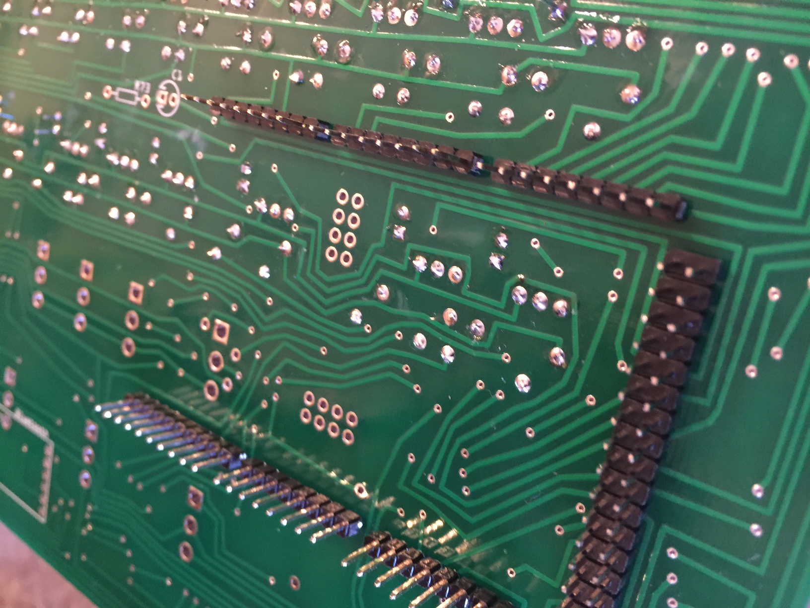
- Make sure you solder the headers facing the underside of the circuit board. Be sure to keep them as straight as you can.
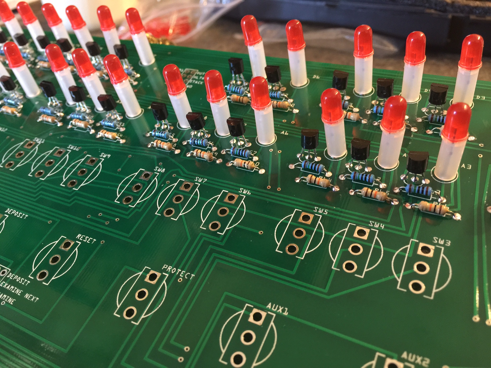
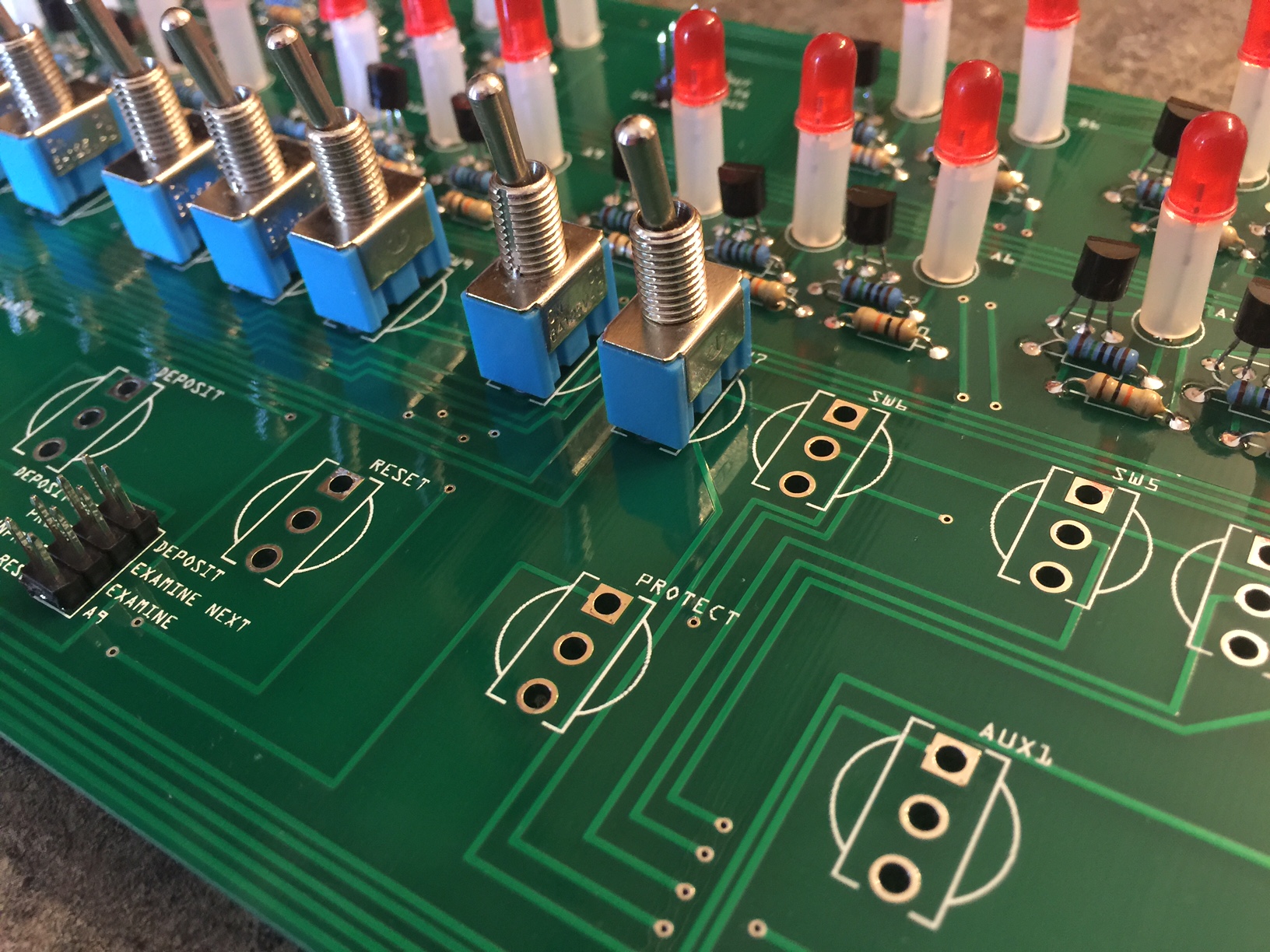
- Add 17 on/off toggle switches to the top row of switches (SW15-SW0), and the power switch (ON/OFF).
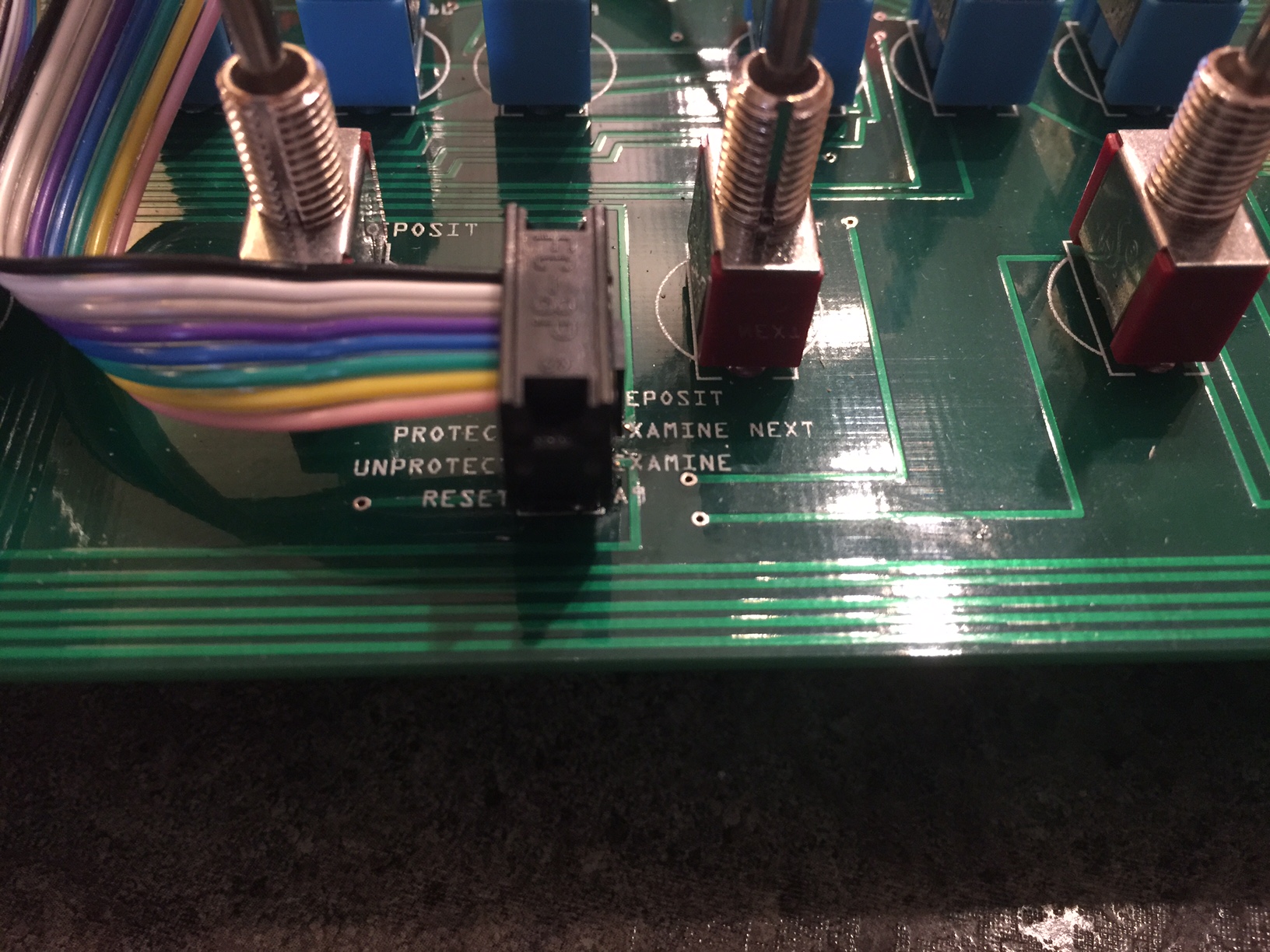
Then add 8 on/off/on toggle switches to the bottom row (STOP, SINGLE, EXAMINE, DEPOSIT, RESET, PROTECT, AUX1, AUX2). Make sure the right type of switches are in the right place! The red switches will probably be a little tighter – you may need to gently rock them side to side to get them in the holes. Or you could use a pliers to squeeze the tabs to make them narrower.
I would suggest putting all switches in place without soldering, then put the front panel in place to verify the alignment of the switches, and then solder them.
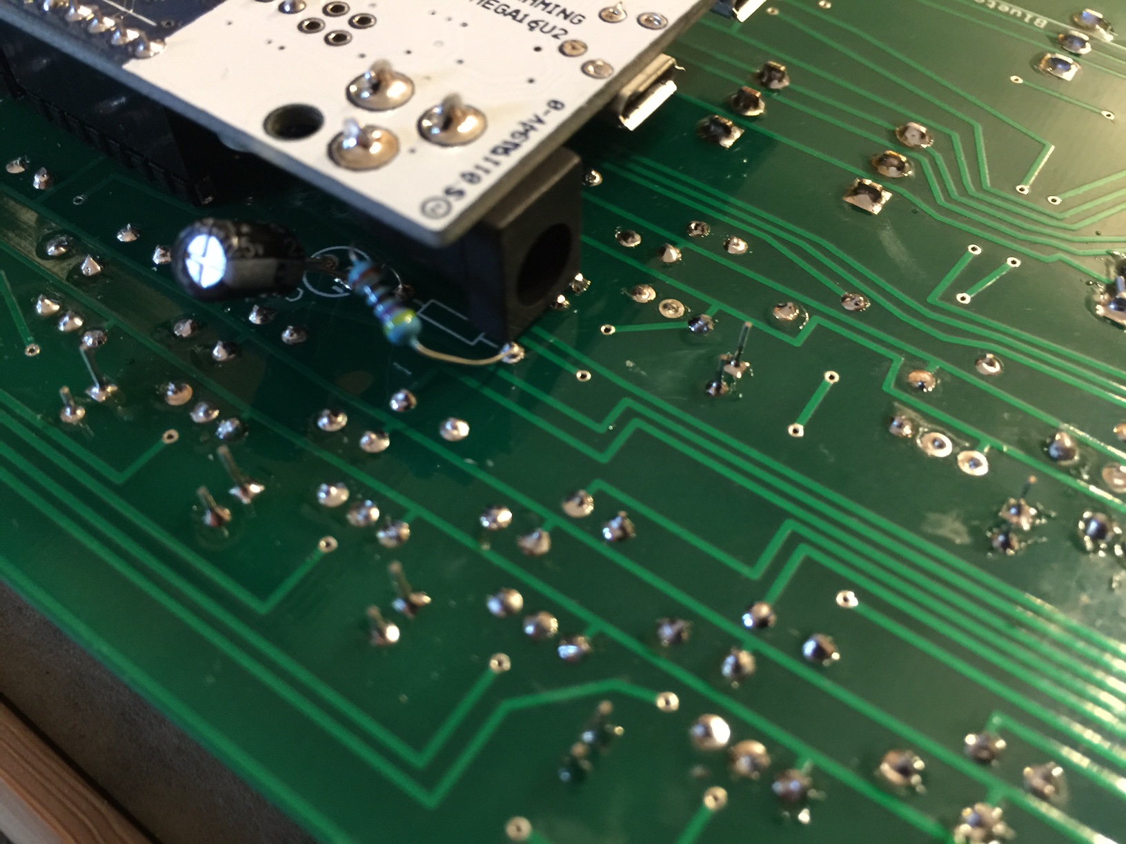
- On the underside of the board, solder the 47µF capacitor (mind the polarity – negative away from the single pin header. Next to it, solder the 470Ω resistor. You should leave these sit a little further from the board than you normally would (see photo).
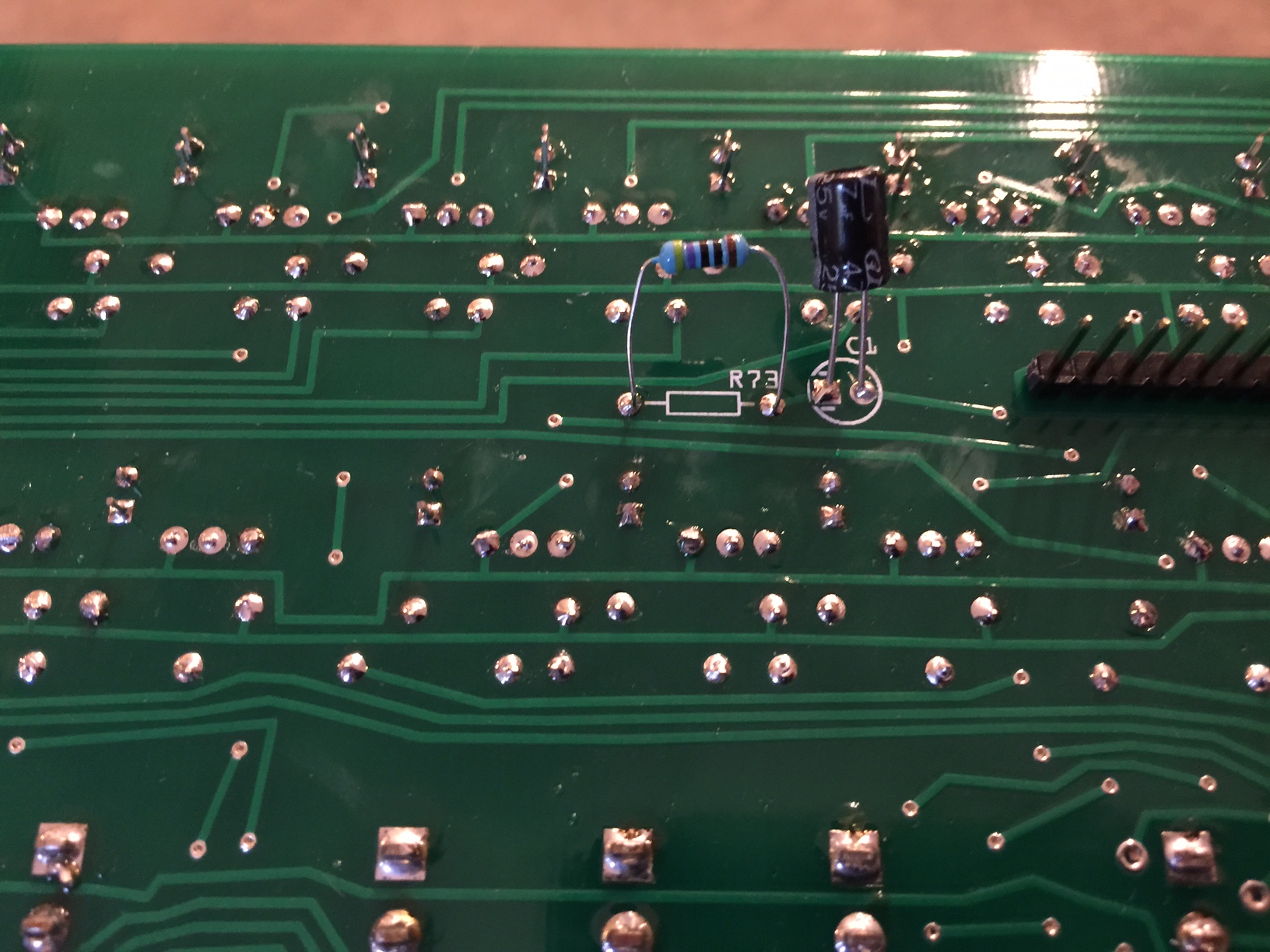
- This is because the Arduino power jack sits about there. Just make sure when they bend over, they don’t touch any other contacts on the circuit board.
If you prefer, you can desolder and remove the power jack. It’s not used in this project.
- On the upper side of the board, add a single jumper wire as shown by the solid line on the circuit board.
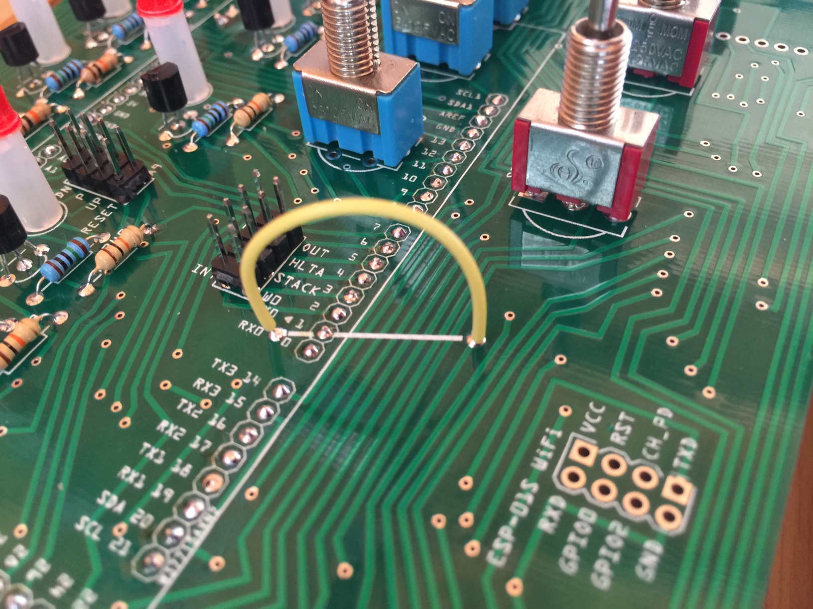
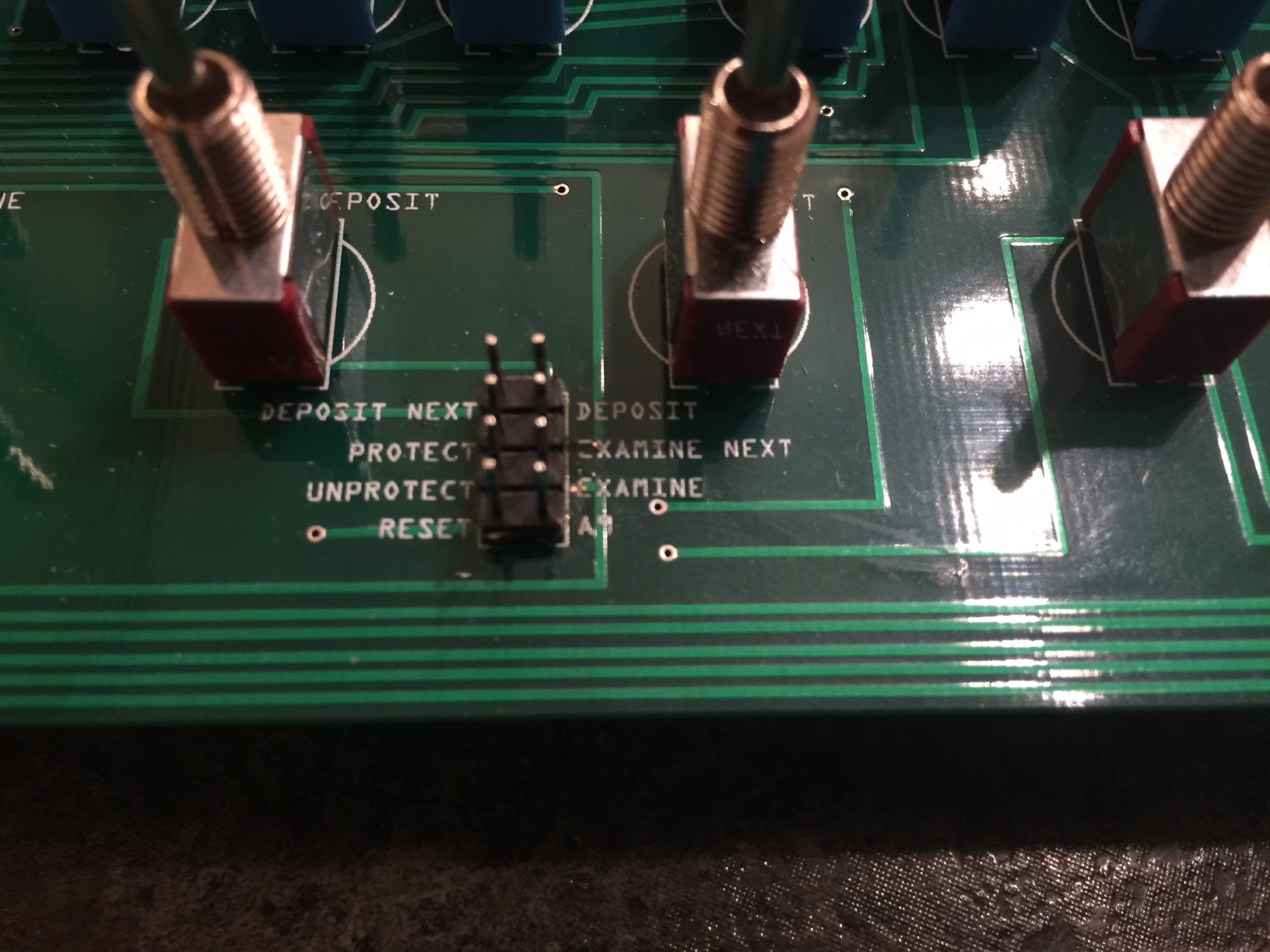
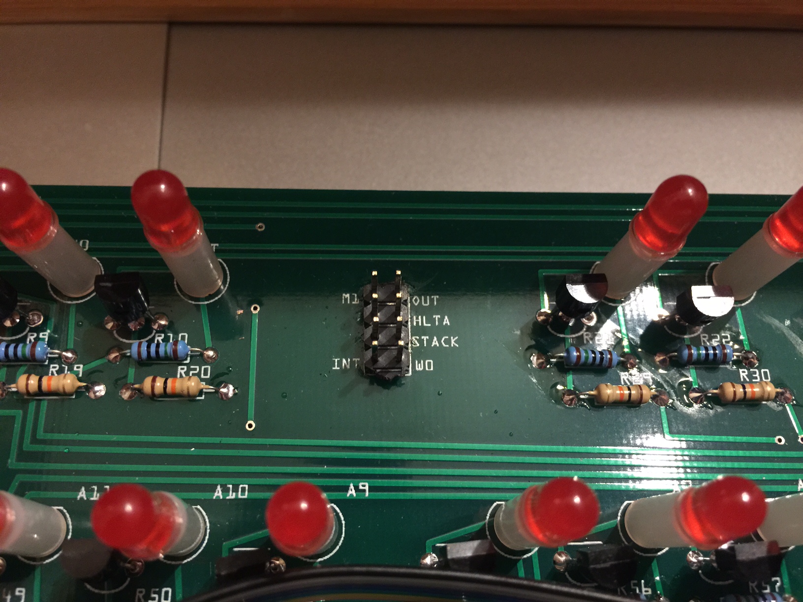
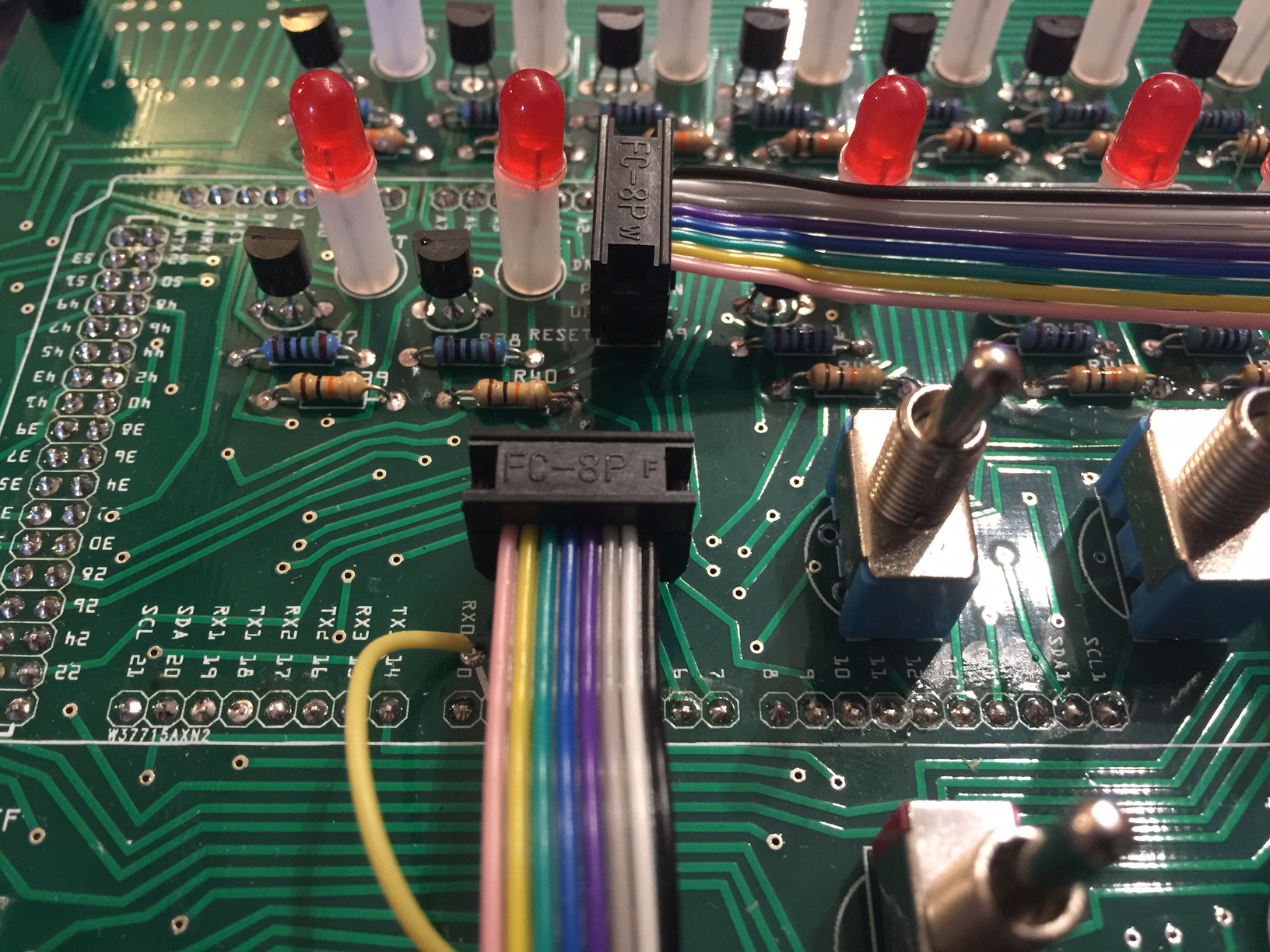
- Break the double pin header into four 8-pin segments. These are a little harder to break, so you may want to try cutting them with a side cutter. Solder them to the upper side of the board in the areas where it says “Reset/A9” and “INT/W0” (four total.)
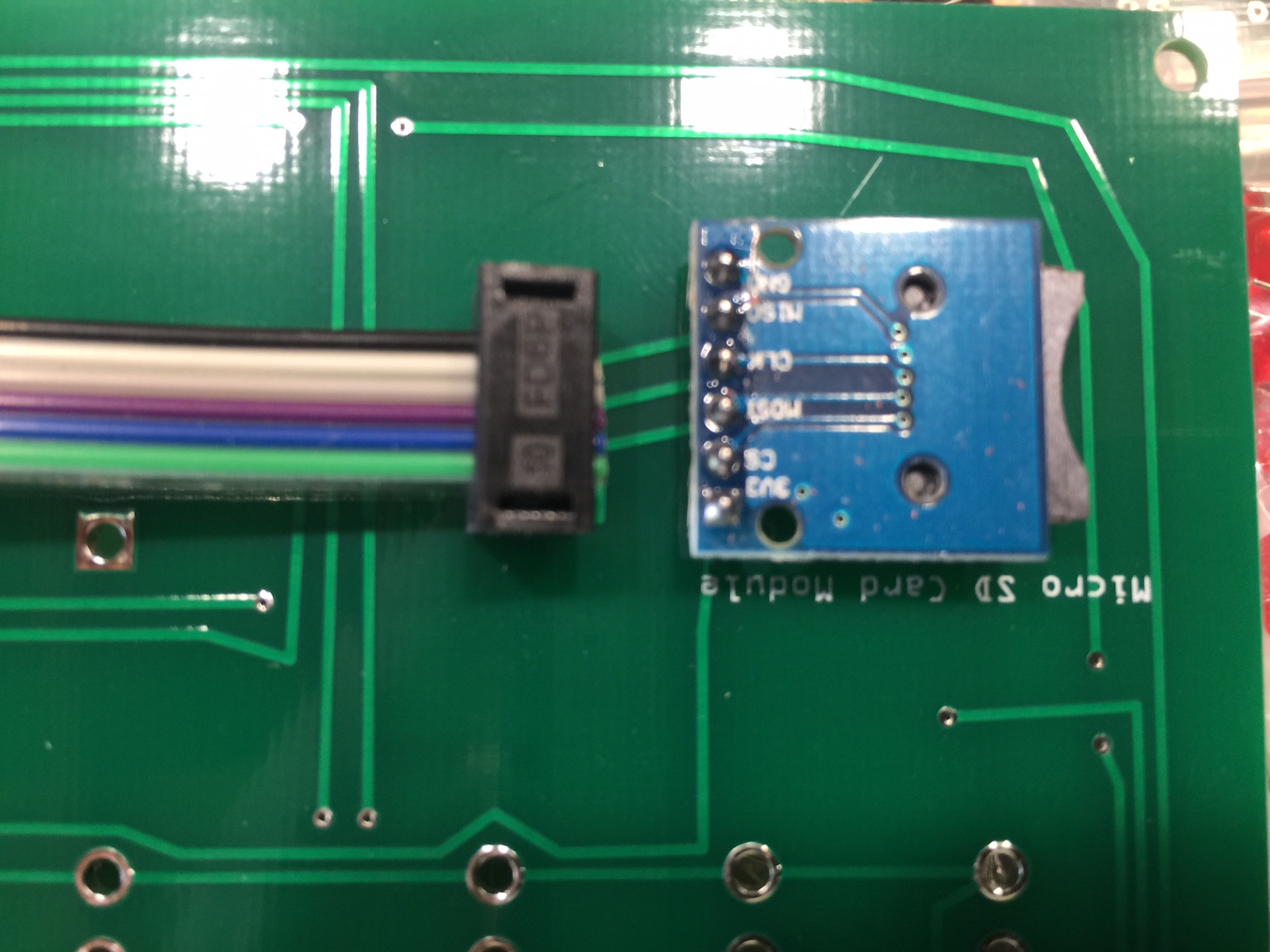
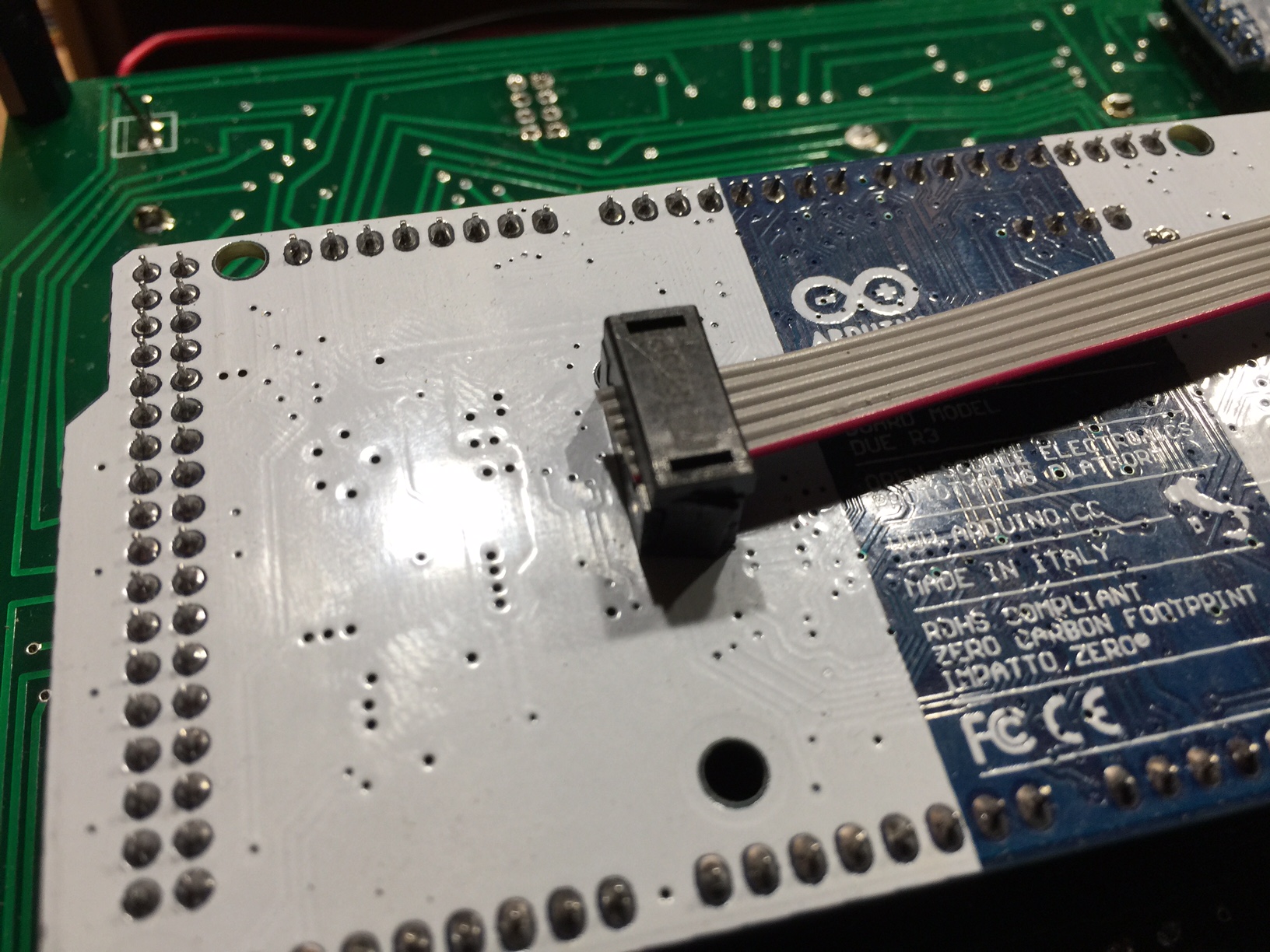
Install the two 8 pin cables with the 4 connectors oriented as shown in the photos.
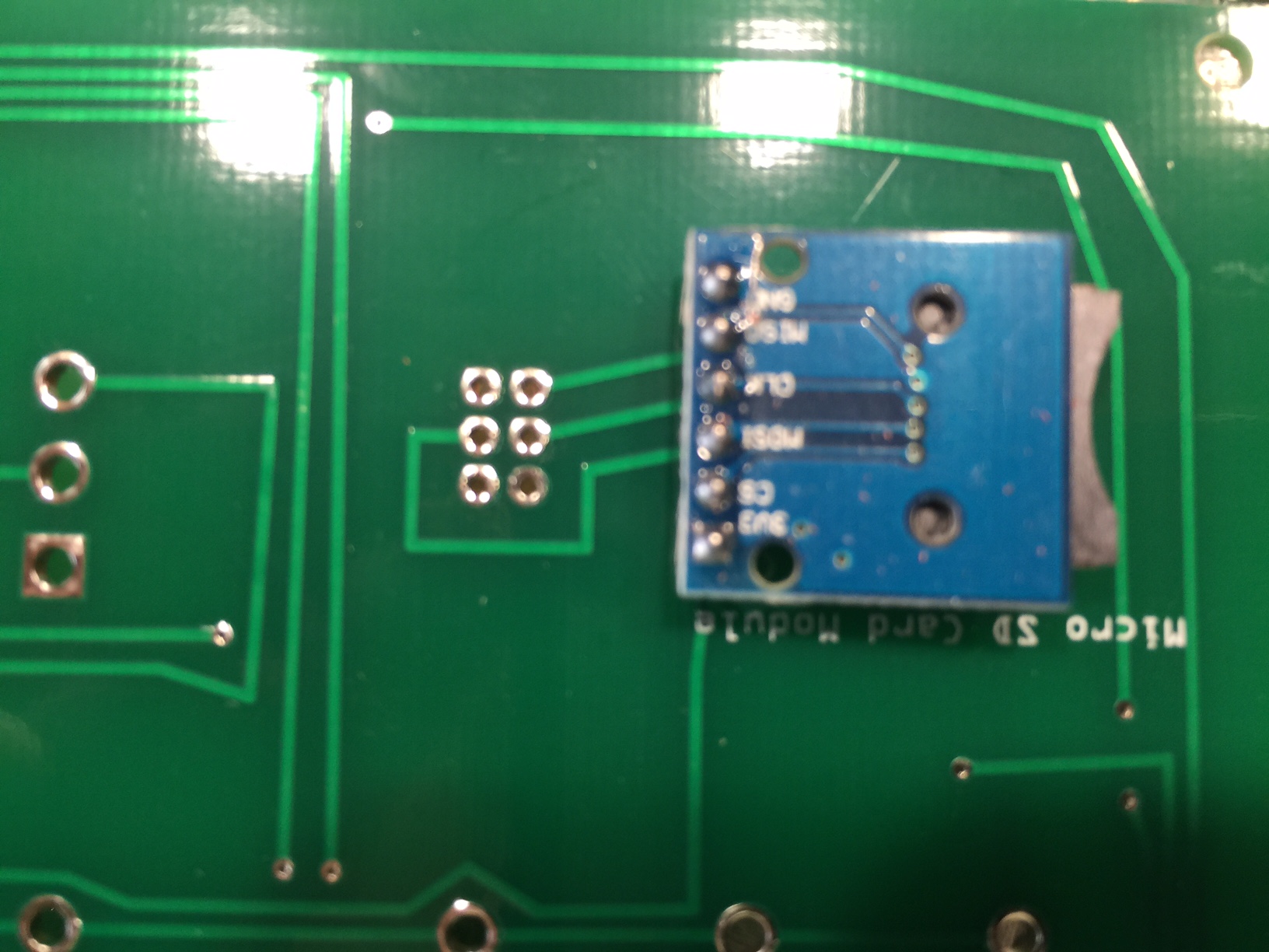
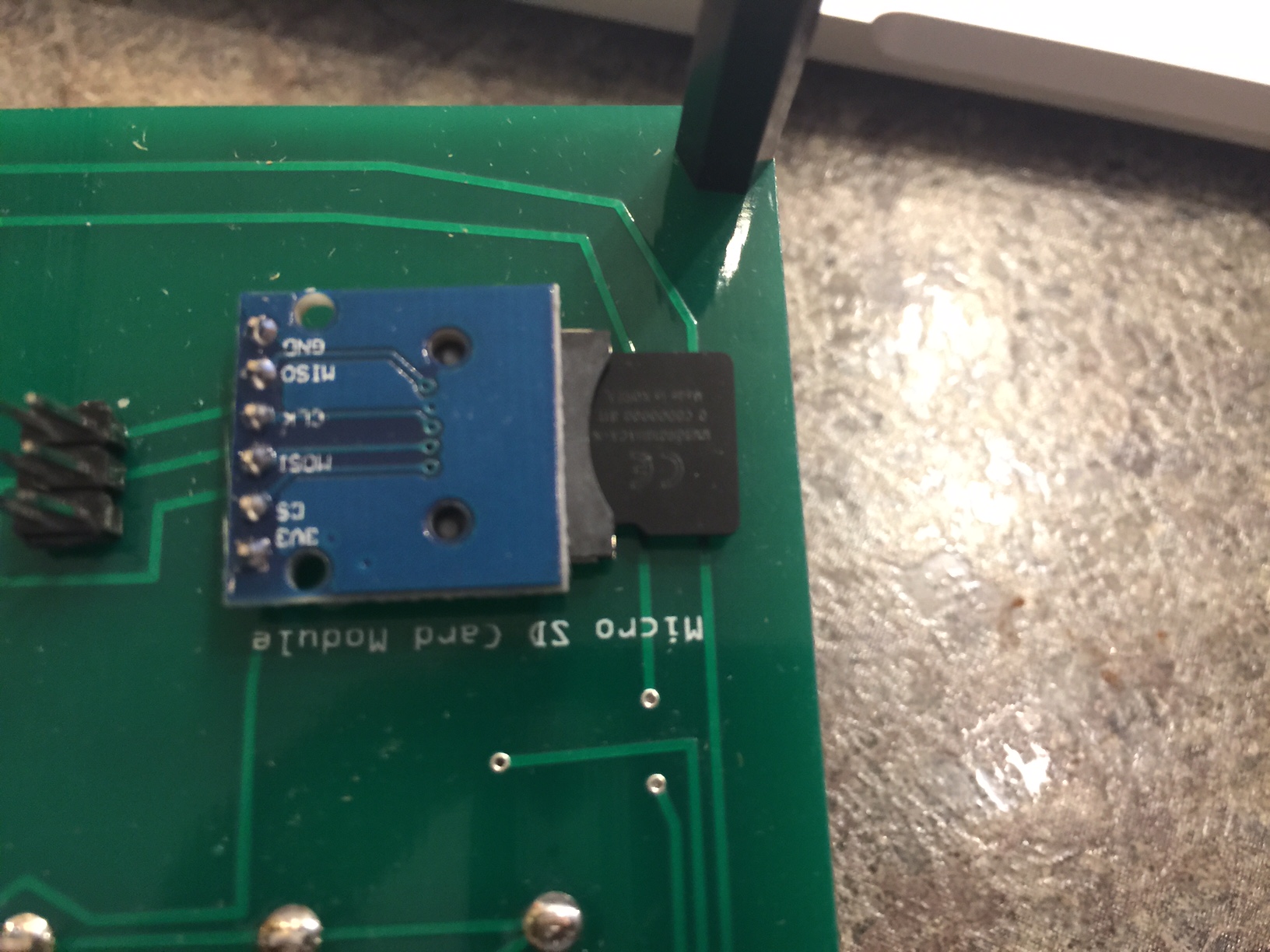
- Solder the Micro SD card module to the underside of the circuit board, using the orientation in the photo.
If you haven’t already (or if you didn’t choose to have your Arduino pre-programmed) you may want to upload the programming to your Arduino now. You can find the instructions on this page.
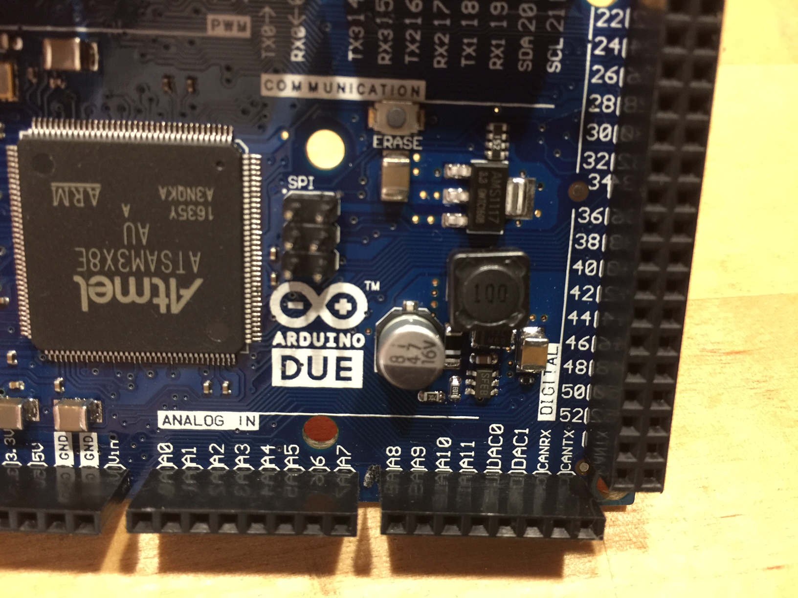
- The next part is optional, but really enhances the operation of your Arduino! You need to connect the Micro SD Module to the SPI connector on the Arduino. Unfortunately, the pins of the SPI connector are facing down toward the circuit board, where there is no room for the connector.
- First, solder the six pin male header to the underside of the board next to the Micro SD Module oriented as shown in the photo.
- If you’re ok desoldering the SPI connector, go ahead and do it, and attach the six pin header connector as shown in the photo.
If you don’t want to desolder the SPI connector, you can simply tack the header onto the top of the SPI pins. This will take some precision soldering, so use your smallest solder tip and a magnifier!
- If you have chosen the HC-05 Bluetooth module, solder that to the underside of the circuit board. You will need to gently bend the module over so the assembly will fit in the supplied project box.
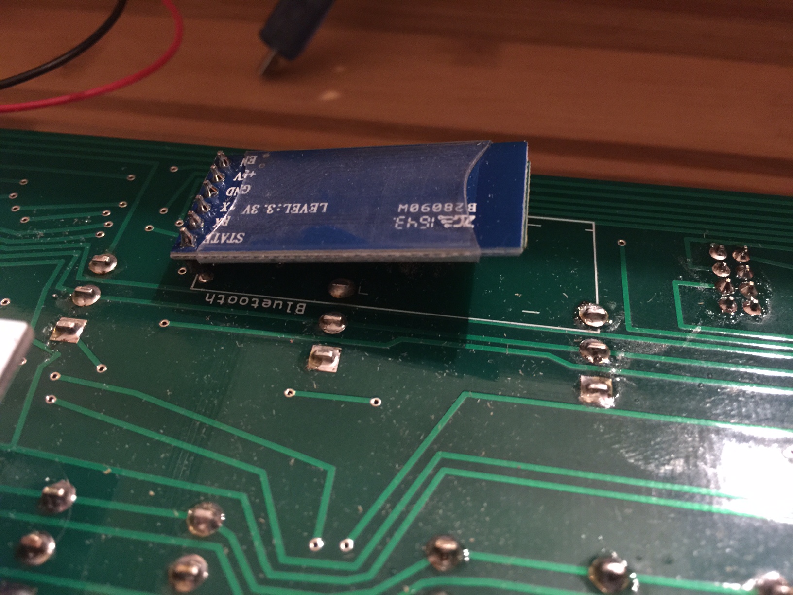
- If you have chosen the MAX3232 DB9 serial module, solder a four-pin male header to the underside of the circuit board, in the middle of the Bluetooth connector (the Bluetooth module uses six pins, solder the header in the middle four pins.)
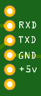
Connect to the MAX3232 module to the four pins from the top of the board down: RXD, TXD, GND, +5v (or VCC.)
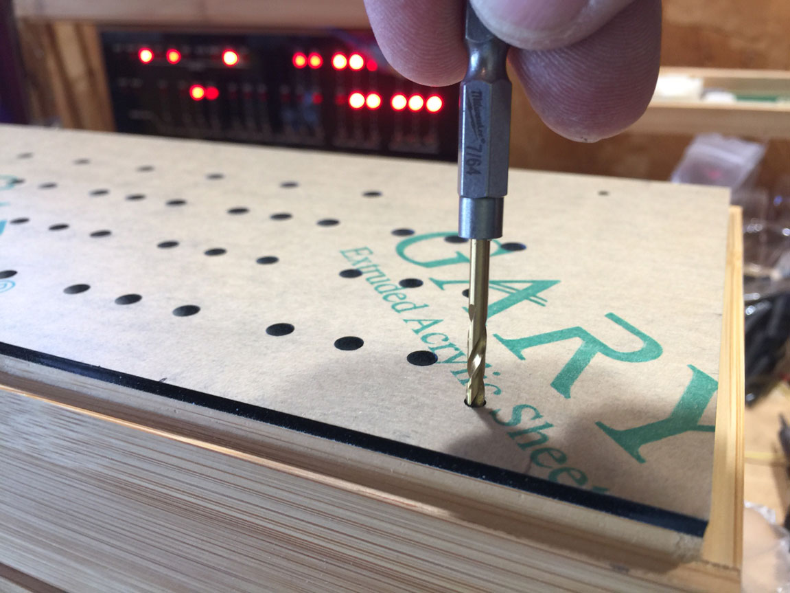
- Place the front panel in the project case and mark the location of the four holes (I like to use a small drill bit to mark where the holes need to be.)
Drill those holes with a 1/8″ (3mm) drill bit.
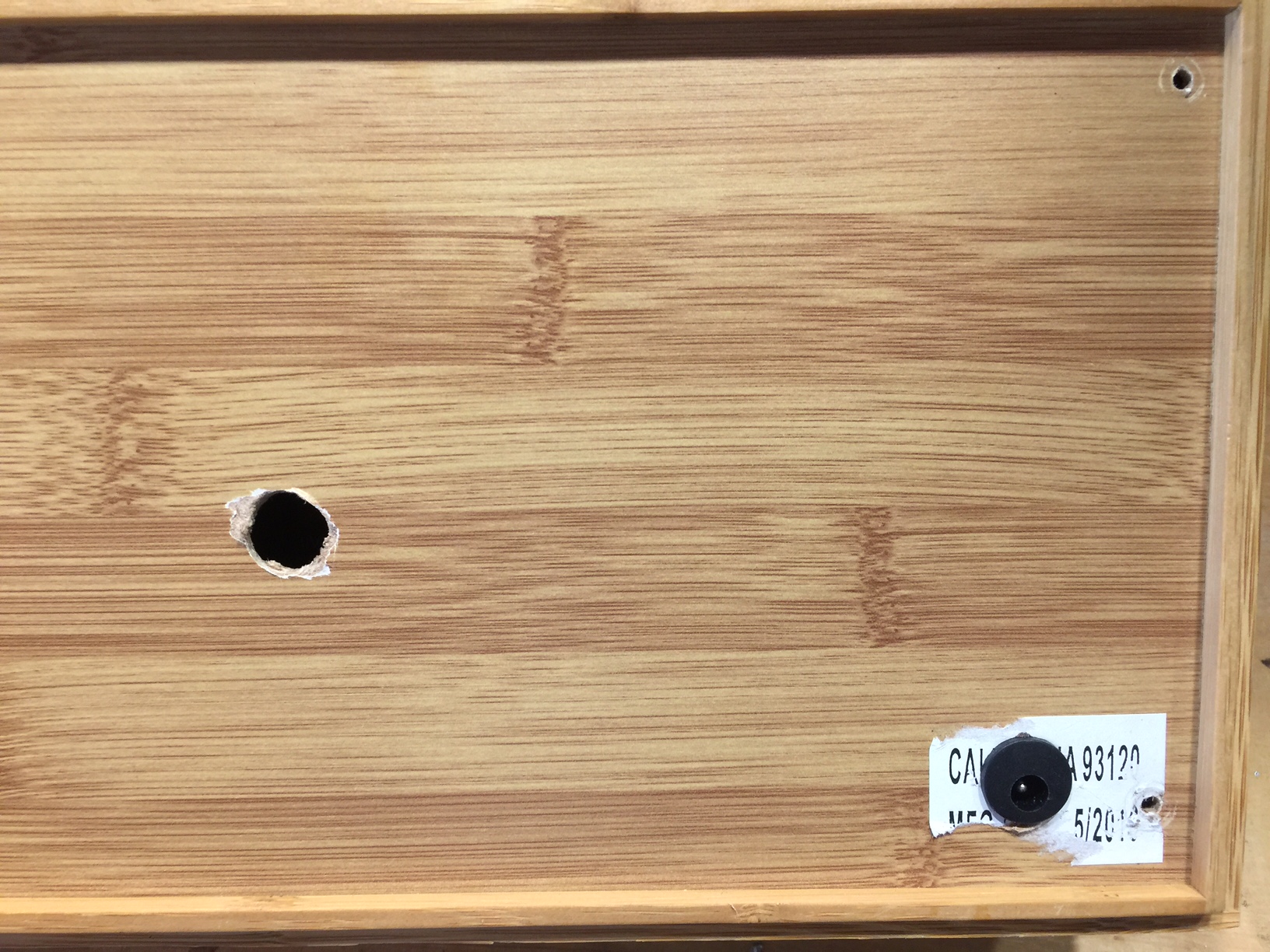
- While you’re drilling holes in the project case, drill a 1/2″ (12mm) hole in the lower left area for the DC jack.
Also drill a 1/2″ (12mm) hole a bit left of center for the USB cable.
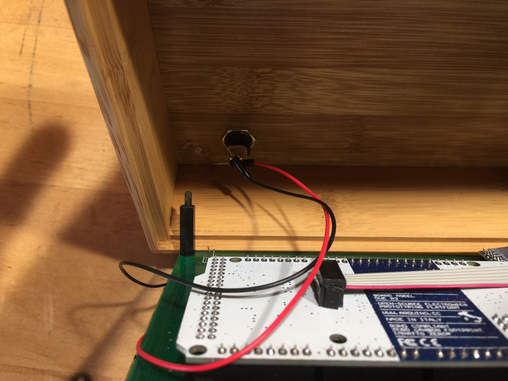
- Solder a short length of parallel stranded wire from the circuit board (lower left) to the power jack. The square solder pad is for the positive (center pin) wire. The other hole is for ground.
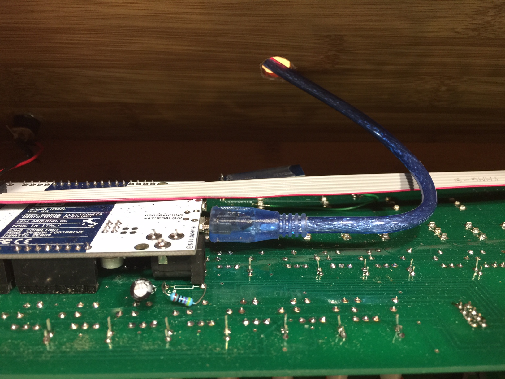
- Plug the Arduino into the circuit board, pass the USB cable through the project box and plug it into the “Programming Port”
When the Arduino is connected to a computer’s USB port, it will draw power from the port and will not need to be connected to a DC power supply.
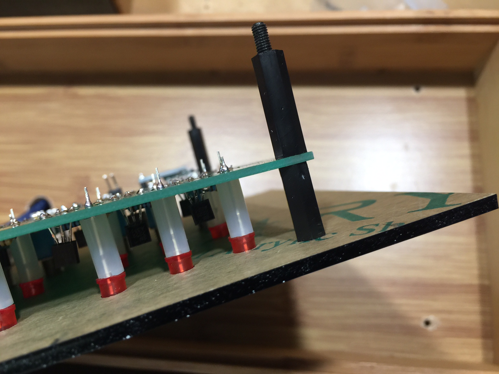
- Attach the 14mm standoff to the topside of the circuit board (with male end down) and screw it into the 20mm standoff on the underside of the circuit board.
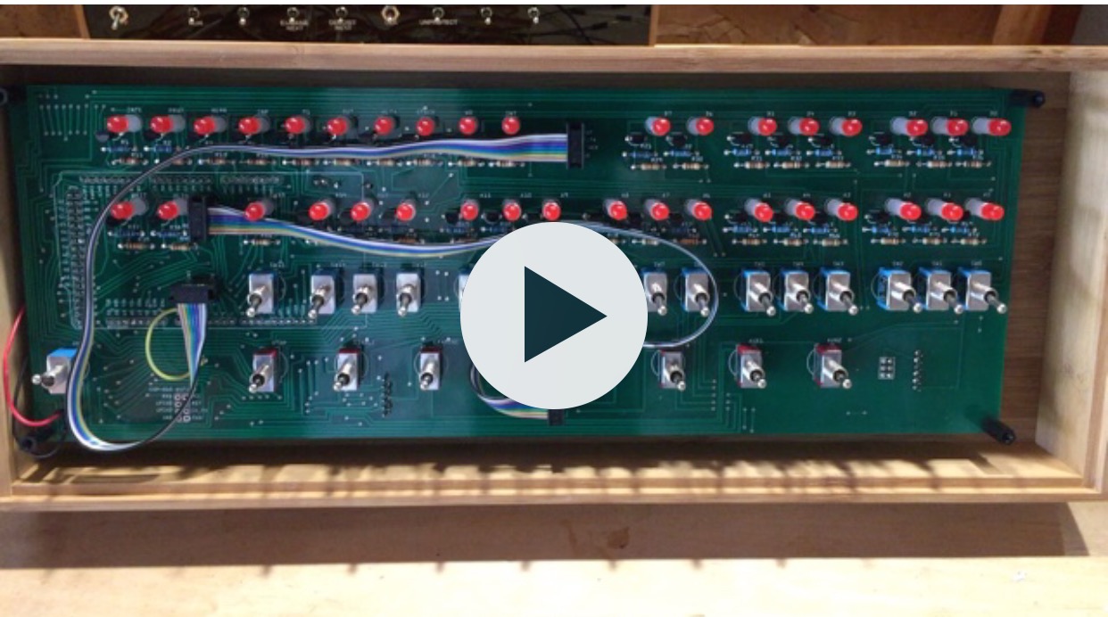
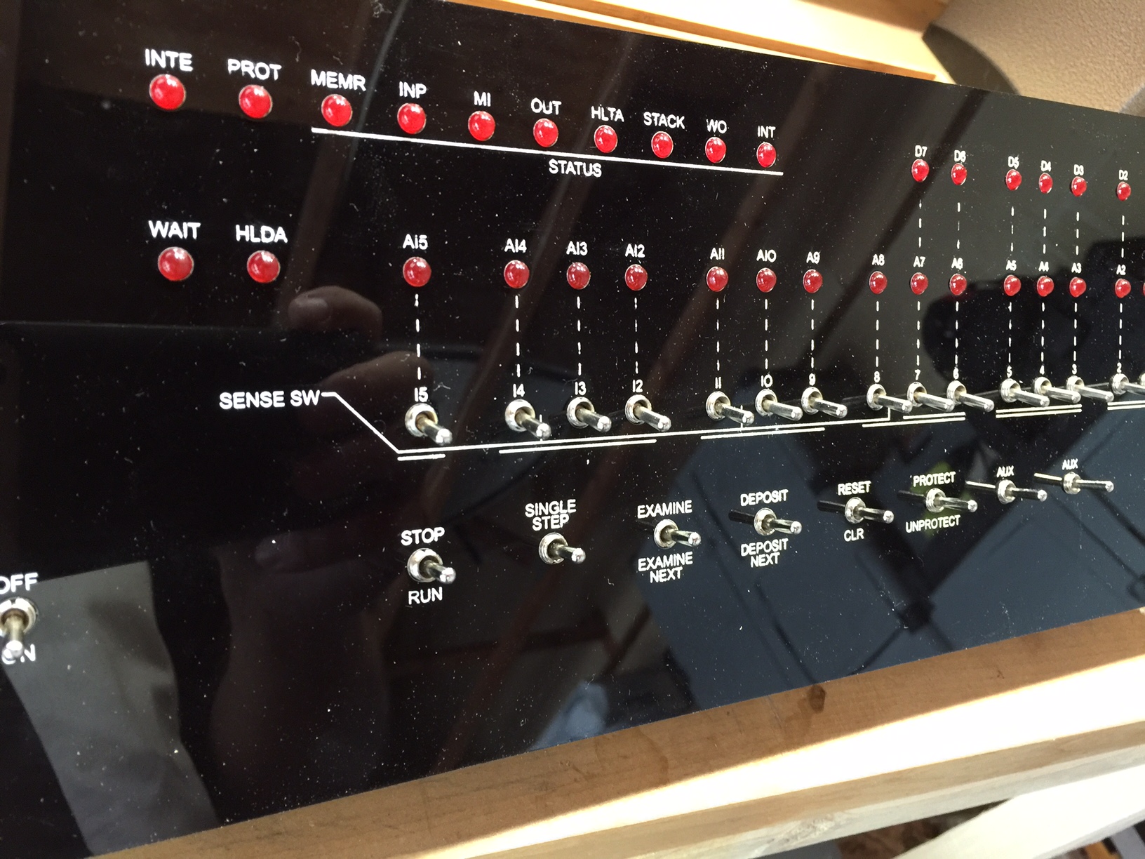
- Before adding the front panel, you will probably want to test you Altair. You should both attach it to the USB port of a computer, and also try powering it with the DC adapter alone. There should be virtually no boot time, the LEDs should all come on, then off, then a random set of LEDs will illuminate.
Watch the video to see what you should expect.
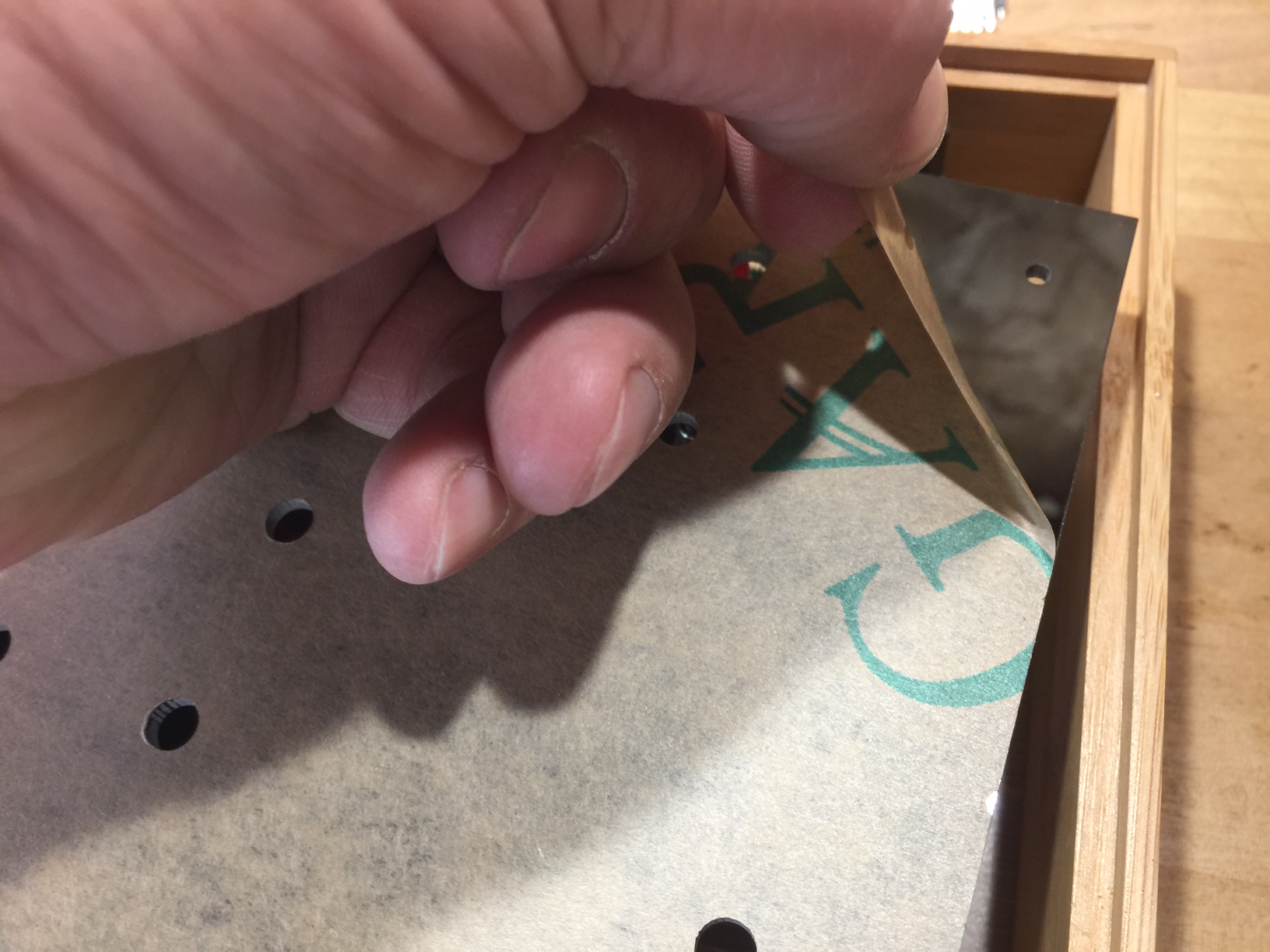
- Remove the mask from the front panel.
I’ve found that if you remove the large piece of mask from the front panel, then soak the panel in water overnight, the rest of the mask (in the “O”, “P”, “A”, etc.) comes of fairly easy with your fingernail – in about 5 minutes you’ll have a clean panel ready to go.
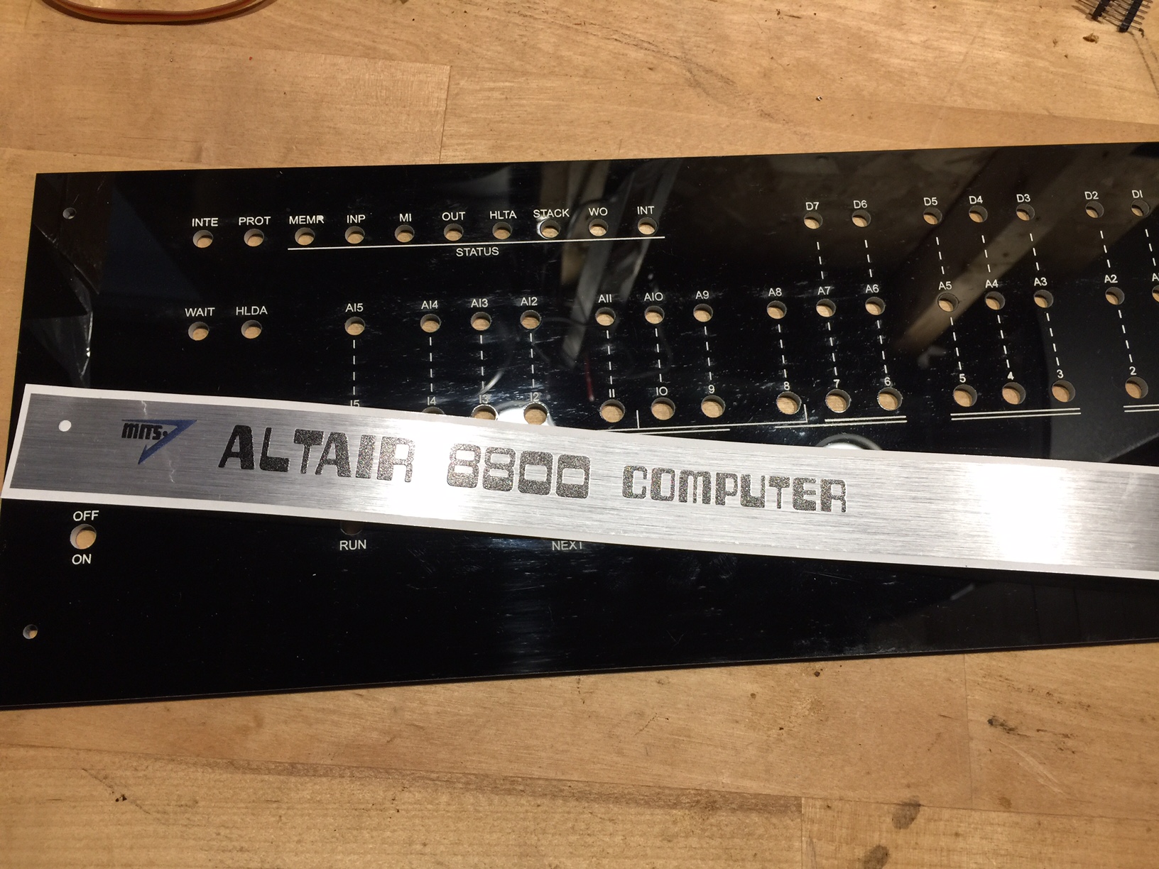
- Apply the metallic “Altair 8800” sticker. Unfortunately (beta!) the holes don’t match the screw holes exactly. Do your best!
- Attach the front panel to the topside of the circuit board. Make sure the standoff holes line up, and the LEDs line up with the appropriate holes. Route the 8 pin ribbon cables so they stay out of the way. You will probably have to apply some force, especially around the threaded switch posts. Add the 3mm nylon screws to keep the front panel in place.
- Copy the Altair disk files to an SD card (1MB is sufficient) and install the SD card in the Micro SD card module. The disk images are available here. From your vantage point, the card will appear upside-down.
HINT: If you have loaded the disk images on the card and see nothing but a non-stop sequence of “c” when you access the card, you need to completely reformat the card (FAT32, be sure to select FULL format, not a quick format.)
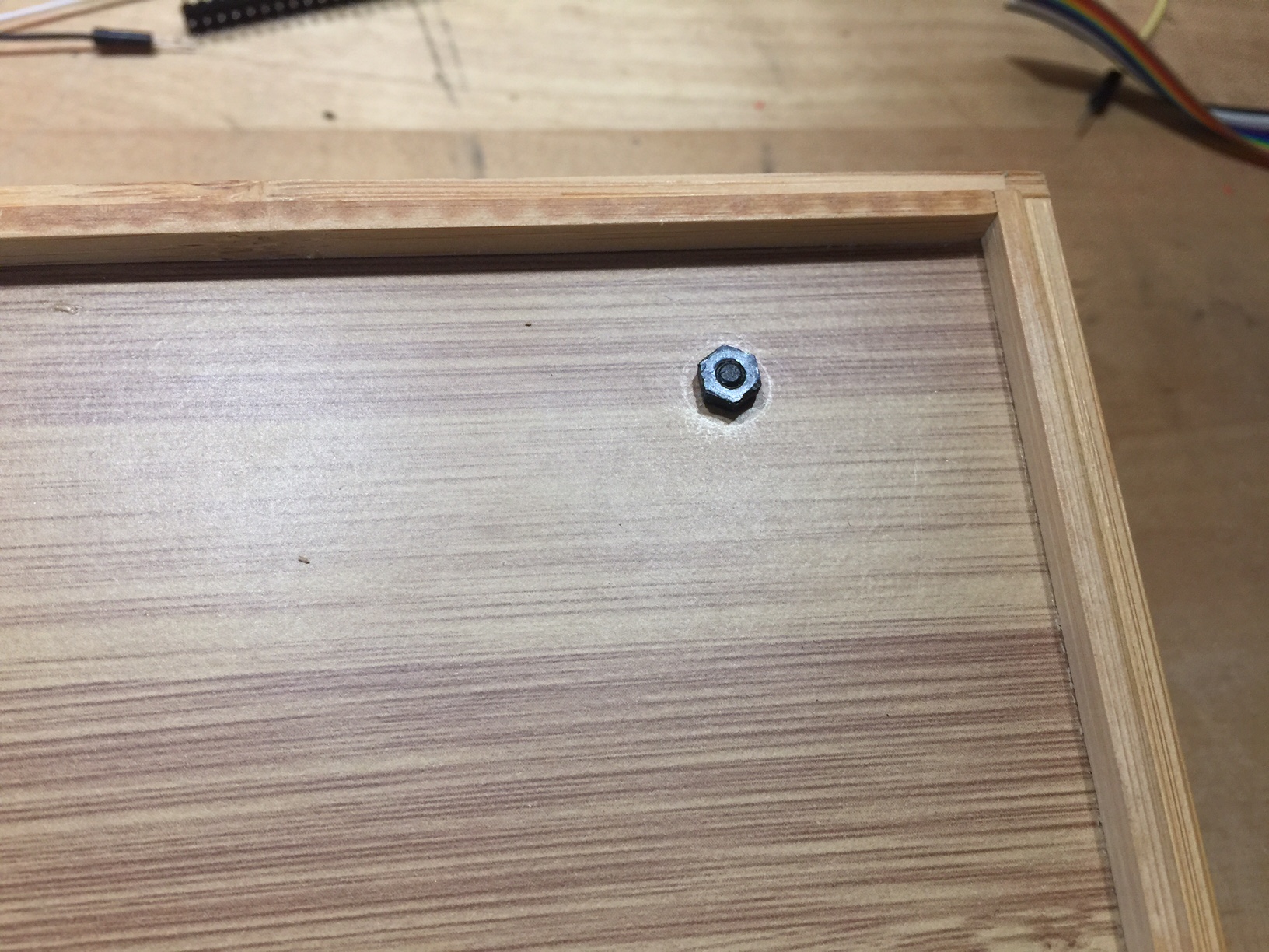
- Place the front panel/circuit board assembly into the project box. The male ends of the 20mm standoffs should protrude through the holes on the bottom of the project box. Secure it in place with 3mm nuts.
If your case seems a little tight (it’s wood so it tends to expand/contract with temperature and humidity) you can easily trim it a bit with an X-Acto knife.